4.16 Oxygen
Face Mask - Industrial
4.16.1 Background
An industrial designer needed to design a new facemask
with some features of an existing facemask. The aim of this study was to
capture the geometry of an existing facemask and apply it in the design
of a brand new oxygen facemask.
Krugersdorp Private Hospital was again approached to perform
the CAT scanning. A series of coronal sections were produced. The data
was retrieved and converted according to the data conversion procedure.
The next step was to supply the data to the designer so that it can be
used in a meaningful method.
4.16.2 Conclusion
This reverse engineering method was successfully applied
to supply the industrial designer with unique results. Again, this method
proved to be the only non-destructive method to perform this reverse engineering
method. The mask was made of Silicon elastomer. No contact type reverse
engineering method could be used to capture the masks geometry. The mask
would deform as the touch probe anticipated to sample 3D coordinate points.
3- and 4-axis laser scanning devices could also not be used due the facemask’s
geometry. The face mask geometry featured a deep undercut where the laser
would not be able to enter. Accuracy again did not prove to play a critical
role in the project that made the CAT scanning method the ideal method
for reverse engineering.
4.16.2.1 Images
 |
 |
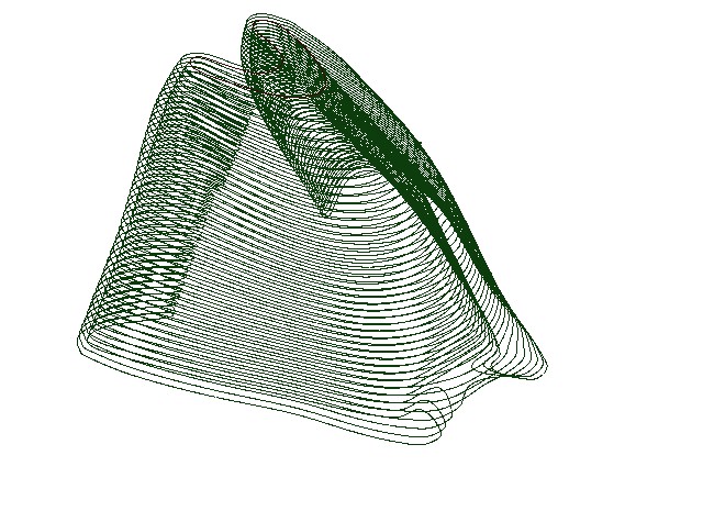
| Figure 4.16.2.1
Isometric view of the cross sections used in the CAD file
to design the new mask.
|
Figure 4.16.2.2
Isometric view of the CAT scanned 3D reconstruction. |
 |
 |
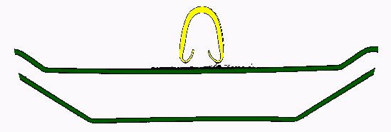
| Figure 4.16.2.3
2D CAT scanned Slice 119 of the face mask(yellow section)
|
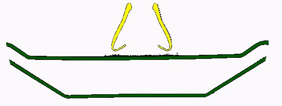
Figure 4.16.2.4
2D CAT scanned Slice 89 of the face mask(yellow section) |
 |
|
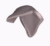
| Figure 4.16.2.5
3D CAT scanned reconstruction of the facemask. Undercut
section. |
|
4.16.3 Oxygen Face Mask
Data Sheet:
| |
Description |
Options (Default) |
Data
|
| 1 |
CT Image Names |
|
CT1-60 |
| 2 |
Patient/Project Name |
|
mask.pat |
| 3 |
Number of First Input Image |
|
1 |
| 4 |
Number of Last Input Image |
|
60 |
| 5 |
Number of First Output Image |
|
000 |
| 6 |
CT or MRI |
CT, MRI |
CT |
| 7 |
Horisontal Nr. Of Image Pixels |
0 to 65535 (265,512,1024) |
512 |
| 8 |
Vertical Nr. Of Image Pixels |
0 to 65535 (265,512,1024) |
512 |
| 9 |
Number of Images per File |
(1) |
1 |
| 10 |
File Swap Format (0,3) |
0,3 |
0 |
| 11 |
Pixel Type |
B,UB,S,US,L,UL,F |
Ccelcint |
| 12 |
Header Size |
*see formula below |
- |
| 13 |
Inter Image Header Size |
0 |
- |
| 14 |
Add Value |
0 to 4095 |
- |
| 15 |
Scale Value |
0 to 4095 |
- |
| 16 |
Table Position |
(mm) |
0 |
| 17 |
Distance Between Slices |
(mm) |
3 |
| 18 |
Slice thickness |
(mm) |
3 |
| 19 |
Pixel Size SQ. |
F.O.R./Nr. Hor. Pixels (mm) |
0.3 |
| 20 |
Gantry Tilt Angle |
Degrees |
0 |
| 21 |
Field of Reconstruction/View |
(mm) |
150 |
| 22 |
Number of Images |
|
60 |
| 23 |
File Size of CAT Image |
kb |
55-60 |
| 24 |
File Size of Converted Image |
kb |
16 |
| 25 |
.3dd file size |
Mb |
0.645 |
| 26 |
.STL file size |
Mb |
4.6 |
| 27 |
RP Method |
(SLA,FDM,OTHER) |
- |
| 28 |
.IGS file size |
Mb |
- |
| 29 |
RP Slice file size |
Mb |
- |
| 30 |
RP Download File size |
Mb |
- |
| 31 |
Grow Time |
Hour |
- |
| 32 |
Tip size |
(T12, T25) |
- |
| 33 |
Slice Thickness |
(0.01", 0.014") |
- |
| 34 |
Finishing Time |
Hour |
- |
| 35 |
Processing Time |
Hour |
5 |
| 36 |
Data Retrieval Time |
Hour |
2 |
| 37 |
Total Cost |
Rand |
=7*100+2500=3200 |

Reverse Engineering Case Studies
Shortcuts back to:
Medical
Studies or
Industrial
& Biological Studies or
Fossil
Studies
or (Back to the Home Page)