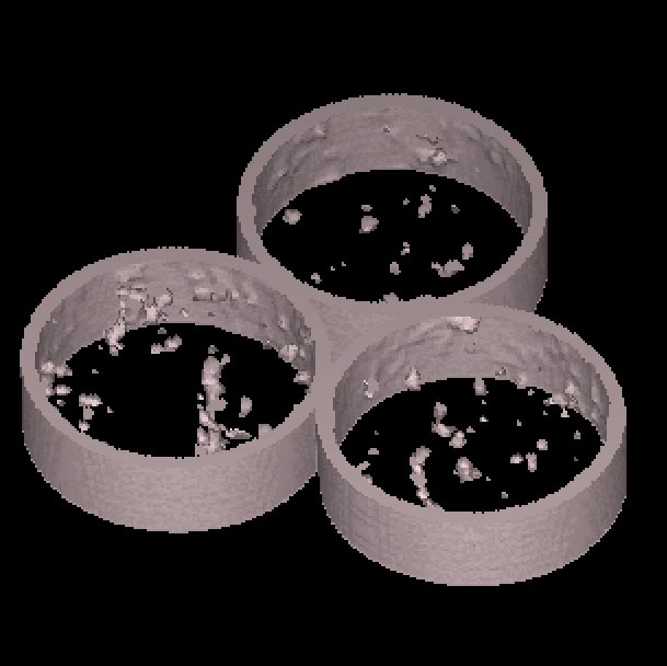

3D reconstructed image of aluminum foam suspended in a
tube.
2D CAT scanned image of the cubical aluminum foam.
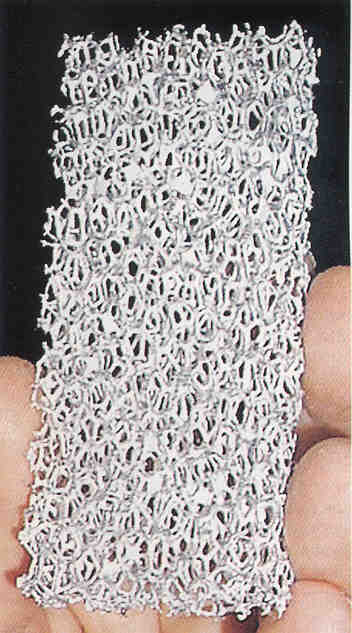
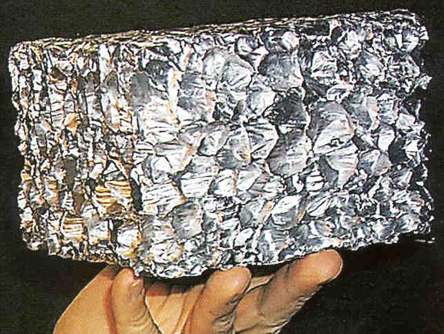
Image of the cubical aluminum foam.
Image of the cubical aluminum foam.
4.13 Aluminum Foam - Industrial
This project was performed for a German engineering student who was completing his doctorate in engineering. This project is automotive related. This project’s aim was to determine the geometry of the foam structure and relate it to the mechanical properties of the material.
Exciting technological advances often first appear in the form of raw materials-the stuff from which either components or entire future systems will be made. That's true for a new type of rigid polyurethane foam developed at Sandia National Laboratories in Albuquerque, and it appears to be the case for the products of a new manufacturing process developed by scientists at the Office of Naval Research (ONR). Under a program sponsored by the ONR, researchers have come up with a low-cost method for manufacturing two types of ultra light porous metals. The lightweight closed-cue and open-cue materials, which reportedly demonstrate excellent strength, heat dissipation, and blast-suppression properties, could end up some day in products ranging from critical aircraft components to bridges and buildings.
Work on lightweight metals isn't new. German and Japanese
automobile manufacturers, such as Audi, are already using them in components
that add structural strength to those products, and concept cars with frames
and fenders made from these exotic materials have been seen at automobile
shows. However, ONR researchers are probing new frontiers, both in the
structural composition of their porous metals and in the range of their
potential applications.
The closed-cell porous metals resemble an ordinary sponge. The cells are evenly sized and spaced holes. The open- cell materials have an appearance similar to the randomly sized and -spaced holes found in a sponge. The size of the holes can be varied to suit the material's intended use.
They actually have very different properties. The closed-cue foams would be very good for thermal insulation; measurements have shown a 400-degree-Centigrade drop across an inch of foam. Potential uses are protecting ammunition magazines or to act as a flame retardant.
The open-cell foams are actually useful for heat dissipation.
The CAT scanning settings play a critical role here. The foam was scanned as three different venues, with varying results. 2D CAT images were checked during scanning. The window settings were optimized on the CT computer. It is again clear that the material what the part is made of plays a major role. The foam materials were prepared in cubes and cylindrical volumetric shapes. The cylindrical shapes were suspended in a cylindrical tube. The tube thickness was about 3mm. Some of the foam sections were less than 0,3mm thick. Due to the great variation in thickness, the cylindrical sections could not be processed successfully. The penetration for the tube was to great to capture the thinner sections. Almost like a over exposed photo.
The cubical sections were scanned and processed successfully. One cube was selected and a STL file was generated. The STL file size was again not manageable by lower level PC hardware.
4.13.2.1 Images
|
|
| Figure 4.13.2.1
3D reconstructed image of aluminum foam suspended in a
tube.
|
Figure 4.13.2.2
2D CAT scanned image of the cubical aluminum foam.
|
|
|
| Figure 4.13.2.3
Image of the cubical aluminum foam. |
Figure 4.13.2.4
Image of the cubical aluminum foam.
|
4.13.3 Aluminum Foam
Data Sheet:
| Description | Options (Default) | Data
|
|
| 1 | CT Image Names | Alfaom.00 | |
| 2 | Patient/Project Name | Alfoam.pat | |
| 3 | Number of First Input Image | 00 | |
| 4 | Number of Last Input Image | 50 | |
| 5 | Number of First Output Image | Alfoam.00 | |
| 6 | CT or MRI | CT, MRI | CT |
| 7 | Horisontal Nr. Of Image Pixels | 0 to 65535 (265,512,1024) | 512 |
| 8 | Vertical Nr. Of Image Pixels | 0 to 65535 (265,512,1024) | 512 |
| 9 | Number of Images per File | (1) | 1 |
| 10 | File Swap Format (0,3) | 0,3 | Ccelcint |
| 11 | Pixel Type | B,UB,S,US,L,UL,F | - |
| 12 | Header Size | *see formula below | - |
| 13 | Inter Image Header Size | 0 | - |
| 14 | Add Value | 0 to 4095 | - |
| 15 | Scale Value | 0 to 4095 | - |
| 16 | Table Position | (mm) | 0 |
| 17 | Distance Between Slices | (mm) | 1 |
| 18 | Slice thickness | (mm) | 1 |
| 19 | Pixel Size SQ. | F.O.R./Nr. Hor. Pixels (mm) | 0.39 |
| 20 | Gantry Tilt Angle | Degrees | 0 |
| 21 | Field of Reconstruction/View | (mm) | 200 |
| 22 | Number of Images | 50 | |
| 23 | File Size of CAT Image | kb | 265 |
| 24 | File Size of Converted Image | kb | 215 |
| 25 | .3dd file size | Mb | 7,*.srf |
| 26 | .STL file size | Mb | 75 |
| 27 | RP Method | (SLA,FDM,OTHER) | - |
| 28 | .IGS file size | Mb | - |
| 29 | RP Slice file size | Mb | - |
| 30 | RP Download File size | Mb | - |
| 31 | Grow Time | Hour | - |
| 32 | Tip size | (T12, T25) | - |
| 33 | Slice Thickness | (0.01", 0.014") | - |
| 34 | Finishing Time | Hour | - |
| 35 | Processing Time | Hour | 16 |
| 36 | Data Retrieval Time | Hour | 3 |
| 37 | Total Cost | Rand | =3500 |
