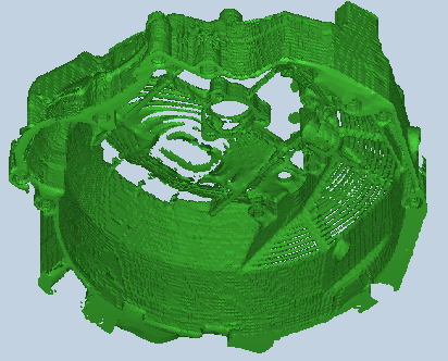

3D Reconstructed Gearbox housing.
3D Reconstructed Gearbox housing.

3D Reconstructed Gearbox housing.
Capturing the geometry of an existing part can play a
critical role if this data can successfully be used for a FEM or process
analysis. The computer modeling and analysis method can the be applied
to assist in the manufacturing process. A 3D electronic format of the part
is required to perform an analysis or process modeling of a manufacturing
process. 3D CAD and STL files existed, but these files proved to be unacceptable
for FEM analysis. The STL file was generated from the 3D CAD file. A new
STL file generated from the CAT scanning data may solve the problem.
The quarter scale SLA prototype was CAT scanned using
the GE. CAT scanner at Hydromed Hospital based in Bloemfontein. The 2D
CAT slices were again stored on 4mm DAT magnetic tape. 2D CAT images of
various positions were stored on film for record.
2D CAT images were checked during scanning. The window settings were optimized on the CT computer. It is again clear that the material what the part is made of plays a major role. The SLA prototype in made of an epoxy polyester. Measurements were taken of the part’s wall thickness and compared to measurements taken from the CAT scan images. In general, the CAT scan images proved to be 0.4 to 2mm thinner than the actual part. Again, the threshold was set to the optimum. Clearly, the SLA material was not suitable to CAT scanning. Referring to an earlier section (3.6), material’s density and atomic number are important factors to obtain an acceptable CAT scan image. A lot of detail was lost at the thinner wall sections and can be seen from the generated 3D images. Due to the material, the process could not be fully evaluated.
4.12.2.1. Images
|
|
|
| Figure 4.11.2
3D Reconstructed Gearbox housing.
|
Figure 4.11.2
3D Reconstructed Gearbox housing. |
|
|
| Figure 4.11.2
3D Reconstructed Gearbox housing. |
4.11.3 Gearbox Housing
Data Sheet:
| Description | Options (Default) | Data
|
|
| 1 | CT Image Names | 1s6I.* | |
| 2 | Patient/Project Name | 1s6I | |
| 3 | Number of First Input Image | E6281S6I1.CT | |
| 4 | Number of Last Input Image | E6281S6I79.CT | |
| 5 | Number of First Output Image | 1S6I1_1.000 | |
| 6 | CT or MRI | CT, MRI | CT |
| 7 | Horisontal Nr. Of Image Pixels | 0 to 65535 (265,512,1024) | 512 |
| 8 | Vertical Nr. Of Image Pixels | 0 to 65535 (265,512,1024) | 512 |
| 9 | Number of Images per File | (1) | 1 |
| 10 | File Swap Format (0,3) | 0,3 | CCGEADVA |
| 11 | Pixel Type | B,UB,S,US,L,UL,F | - |
| 12 | Header Size | *see formula below | - |
| 13 | Inter Image Header Size | 0 | - |
| 14 | Add Value | 0 to 4095 | - |
| 15 | Scale Value | 0 to 4095 | - |
| 16 | Table Position | (mm) | 0 |
| 17 | Distance Between Slices | (mm) | 1 |
| 18 | Slice thickness | (mm) | 1 |
| 19 | Pixel Size SQ. | F.O.R./Nr. Hor. Pixels (mm) | 0.47 |
| 20 | Gantry Tilt Angle | Degrees | 0 |
| 21 | Field of Reconstruction/View | (mm) | 240 |
| 22 | Number of Images | 79 | |
| 23 | File Size of CAT Image | kb | 270-280 |
| 24 | File Size of Converted Image | kb | 11-23 |
| 25 | .3dd file size | Mb | 3.2 *.srf |
| 26 | .STL file size | Mb | 17 |
| 27 | RP Method | (SLA,FDM,OTHER) | SLA |
| 28 | .IGS file size | Mb | - |
| 29 | RP Slice file size | Mb | 19 |
| 30 | RP Download File size | Mb | 16 |
| 31 | Grow Time | Hour | 6 |
| 32 | Tip size | (T12, T25) | - |
| 33 | Slice Thickness | (0.01", 0.014") | 0.01" |
| 34 | Finishing Time | Hour | 3 |
| 35 | Processing Time | Hour | 2 |
| 36 | Data Retrieval Time | Hour | 2 |
| 37 | Total Cost | Rand | =8*250=2000 |
