4.6 Human Pelvis
- Medical
The hipbone is attached to the vertebral column (backbone)
by the five sacral vertebrae, which become fused together in the adult
to form the sacrum.
The hip joint is on the side of the hipbone, rather than
underneath it. At the hip joint, there is a deep socket for the head of
the femur (thighbone). This provides more space for the muscles on the
inner side of the thigh.
The knee joints are closer to a middle line drawn vertically
through the body. This means the knees are closer to the center of gravity
of the body and give more stability. The femur, therefore, has to run inward,
as well as downward, to meet the knee joint.
The femur (thighbone) forms the upper part of the leg.
It not only supports the body when standing, but is also used when walking,
running, jumping, climbing or squatting. Therefore, it is the largest and
strongest bone in the body.
The femur is also the longest bone, making up over a quarter
of a human being's total height. Its size makes the femur very liable to
injury.
The rounded upper end of the femur meets the hipbone at
the hip joint, which is a ball-and-socket joint. A narrower neck runs sideways
and downward to meet the shaft of the bone. Near the upper end of the femur
are two projections, and it is here that muscles attach to the bone. At
the lower end of the bone, two rounded surfaces fit into two small hollows
on the upper end of the tibia (main shinbone). This forms the knee joint.
[36], [37]
Reference [40] p20, recommend 10mm slice thickness with
10mm table feed. Reconstruction to thinner slice thickness will be required
for realistic imaging. CAT parameters such as 300mm F.O.V., 120kV and 50
to 100mA can be used.
4.6.1 Background
A male patient required a hip transplant. The orthopedic
surgeon was contacted and it was suggested that it will be of great value
to capture the geometry of the pelvis to determine if there is sufficient
bone structure required for an operation of this nature. The patient was
scanned at Morningside clinic with the aid of their Toshiba Spiral X-Vision/GX
CAT scanner.
Permission was granted so that this patient’s data may
be retrieved from the CAT scanner. Please refer to section (3.7.4) for
the data retrieval procedures. Morning Side Clinic prepared a 3D visualization
of the scanned area. The spiral data was prepared in two sets to evaluate
the difference. The radiology firstly prepared one set of 3mm thick slices
and 3mm intervals or spacing. The finest possible slice thickness and slice
spacing were requested to achieve the best results. In this case it would
be better to sample more data than required. The right hand pelvis and
femur were in a developed state of deterioration. The orthopedic surgeon
was particularly interested in the left-hand pelvis. For a successful hip
replacement, sufficient bone structure is required at the back of the pelvis.
It was quite clear that the front side of the pelvis did not have sufficient
bone structure. The most probable cause of the poor state of the pelvis
could be a form of austioporouses. The data processing of this case was
particular difficult. The fiber, soft tissue and muscle suspended bone
particles. The pelvis needed to separate from the other bone and soft tissue.
The pelvis and femur were hardly recognizable in certain areas. It was
therefor difficult to decide what bone structure is part of the pelvis
and what part is suspended by soft tissue The orthopedic surgeon provide
a left-hand side of a real human pelvis for reference. CAT scanned film
was also provided with 2D slice information as well as 3D rendering to
be used for verification.
The data was then processed and a meeting was arranged
with the orthopedic surgeon, to verify the results of the computer screen.
He was please with the results and requested that we continue with the
next phase of the project.
The next stage was to create a prototype of the pelvis.
The 3dd file was used with the Materialise, CTM software to generate a
STL format file. The STL file was then used with the Stratasys QuickSlice
software. Horizontal slices were created. The software performed support
generation, automatically. The SML file was created. The FDM machines use
this data to build a prototype. The prototype was grown with the red ABS
plastic material and finished by removing the support structure generated
by the FDM process.
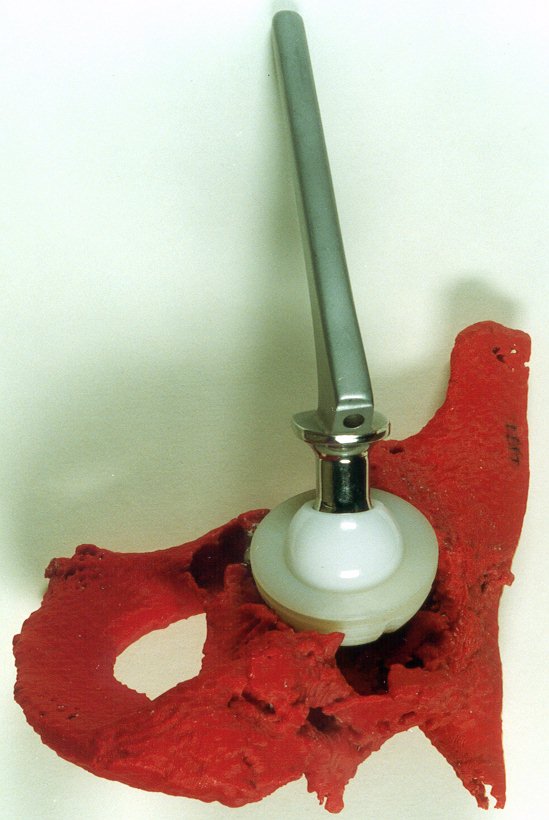
The prototype of the pelvis was supplied to the orthopedic
surgeon. He later fitted temporarily a cup to the pelvis prototype with
the aid of a bonding putty called prestik, to display the principle of
fitting the cup into the pelvis. Areas where bone and bone cement would
normally be filled were left out to view the detail of the pelvis’s condition.
4.6.2 Conclusion
Delivery time and cost are again the most important factors.
The acceptable delivery time for a pelvis case study would be 3 to 5 days.
The cost also needs to be affordable. Some of patients are capable to pay
for the cost of this technology themselves, but not all patients are so
fortunate.
The finest resolution was selected to produce the prototype.
It was the first medical case study and needed to capture as much detail
as possible to demonstrate the technology. The time of 110 hours to build
the prototype can be reduced to a third. The cost for this phase will drop
accordingly. The total project time of 126.7 hours can be reduced to only
53.3 hours in future. It will be very important to deliver prototypes in
as short as possible turn around time.
It was of great value to have the 2D and 3D CAT scanned
film print outs for verification. It was also used for determining the
patient's orientation as well as dimensional inspection.
Data retrieval should be more automated or will need to
be performed after hours to avoid any interference with the radiology team’s
daily workload.
A fathom need to be obtained for physical data verification
in future.
Measurements, in the xy axis, from the CAT scan film at
the -133 mm position was compared with the converted Mimics slice at approximately
the same position. Measurements were taken with the aid of a caliper, from
the CAT scan film, and with the aid of the mouse position from the Materialise
software. The scale was determined for the CAT film images to be 4.35:1,
thus 1mm on the film represented actually 4.35 mm. Measurements were compared
varied 1mm in 45mm or about 2%. A second measurement proved better results,
3.13mm over a 280mm distance, or 1.1% deviation.
Measurements were also taken in the z-axis. A new scale
was determined and the deviation proved to be 3.33mm for a distance of
17.53mm, of 19%. It was not easy to find the same position to compare the
dimensions and the variation may be due to that. It may also be due to
the overlap of the scanned slice data. A comparison of the measurements
was taken from the 3D constructions made by Morningside Clinic and compared
to the 2D-slice position of the converted Mimics Data.
4.6.2.1 Images
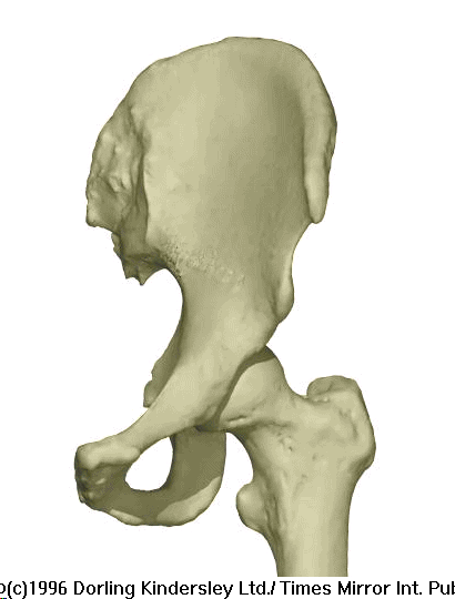
|
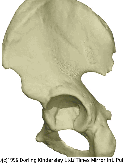
|
| Figure
4.6.2.1
The Human Pelvis and Femur.
|
Figure 4.6.2.2
The Human Pelvis. |
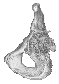
|
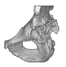
|
| Figure 4.6.2.3
3D reconstruction of the patient’s Pelvis.
|
Figure 4.6.2.4
3D reconstruction of the patient’s Pelvis. |
 |
 |
| Figure 4.6.2.5
FDM prototype of the patient’s Pelvis with prosthesis
fitted. |
Figure 4.6.2.6
FDM prototype of the patient’s Pelvis with prosthesis
fitted. |
4.6.3 Pelvis Data Sheet:
| |
Description |
Options (Default) |
Data
|
| 1 |
CT Image Names |
|
566:227 - 527 |
| 2 |
Patient/Project Name |
|
hip3 |
| 3 |
Number of First Input Image |
|
566:227 |
| 4 |
Number of Last Input Image |
|
566:526 |
| 5 |
Number of First Output Image |
|
hip3.000 |
| 6 |
CT or MRI |
CT, MRI |
CT |
| 7 |
Horisontal Nr. Of Image Pixels |
0 to 65535 (265,512,1024) |
512 |
| 8 |
Vertical Nr. Of Image Pixels |
0 to 65535 (265,512,1024) |
512 |
| 9 |
Number of Images per File |
(1) |
1 |
| 10 |
File Swap Format (0,3) |
0,3 |
0 |
| 11 |
Pixel Type |
B,UB,S,US,L,UL,F |
S |
| 12 |
Header Size |
*see formula below |
8704 |
| 13 |
Inter Image Header Size |
0 |
0 |
| 14 |
Add Value |
0 to 4095 |
2048 |
| 15 |
Scale Value |
0 to 4095 |
1.1 |
| 16 |
Table Position |
(mm) |
0 |
| 17 |
Distance Between Slices |
(mm) |
0.5 |
| 18 |
Slice thickness |
(mm) |
3 |
| 19 |
Pixel Size SQ. |
F.O.R./Nr. Hor. Pixels (mm) |
0.71 |
| 20 |
Gantry Tilt Angle |
Degrees |
0 |
| 21 |
Field of Reconstruction/View |
(mm) |
364 |
| 22 |
Number of Images |
|
257 |
| 23 |
File Size of CAT Image |
kb |
215 |
| 24 |
File Size of Converted Image |
kb |
215 |
| 25 |
.3dd file size |
Mb |
0.742 *.3dd |
| 26 |
.STL file size |
Mb |
34.62 , pellft.stl |
| 27 |
RP Method |
(SLA,FDM,OTHER) |
FDM |
| 28 |
.IGS file size |
Mb |
- |
| 29 |
RP Slice file size |
Mb |
34.19, pellft.ssl |
| 30 |
RP Download File size |
Mb |
34.46 |
| 31 |
Grow Time |
Hour |
109.9 |
| 32 |
Tip size |
(T12, T25) |
T12 |
| 33 |
Slice Thickness |
(0.01", 0.014") |
0.01" |
| 34 |
Finishing Time |
Hour |
6 |
| 35 |
Processing Time |
Hour |
5 |
| 36 |
Data Retrieval Time |
Hour |
4 |
| 37 |
Total Cost |
Rand |
=109.9*100+6*55+9*150
=12670 |
 Reverse Engineering Case Studies
Shortcuts back to:
Medical
Studies or
Industrial
& Biological Studies or
Fossil
Studies
or (Back to the Home Page)